





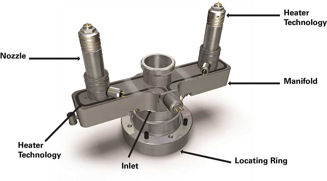
Injection Molding Runner System Design
When manufacturing plastic products at scale, multi-cavity injection molds offer tremendous efficiency advantages. Picture a mold that can produce sixteen identical parts in one go rather than just one. The challenge isn't simply cutting multiple cavities into the steel-it's ensuring that molten plastic flows into each cavity with perfect consistency. This balance determines whether your parts will have uniform dimensions, consistent quality, and minimal internal stress.
The runner system acts as the circulatory network of an injection mold, channeling hot plastic from the machine nozzle through various paths until it reaches each cavity. Getting this right matters more than most people realize. When the flow becomes imbalanced, some cavities fill faster than others, creating products with different internal stresses and potentially different dimensions. For manufacturers, this translates directly into rejection rates, wasted materials, and compromised product reliability.
Traditional approaches to runner design have relied heavily on experience and trial-and-error methods. Engineers often start with an H-type runner configuration because it provides geometrically equal path lengths to each cavity. However, geometry alone doesn't guarantee balanced flow. As molten plastic travels through the runners, friction generates heat-what engineers call shear heating. This phenomenon causes the plastic's viscosity to change, creating flow imbalances even in perfectly symmetrical runner layouts. The problem intensifies as you increase the number of cavities, making the H-type approach less reliable for larger production runs.
Computer simulation software has become increasingly popular for optimizing runner systems. While powerful, these tools present their own challenges. Without solid engineering principles guiding the process, designers can spend excessive time running iterations, essentially conducting digital trial-and-error rather than informed optimization. The computational approach also tends to obscure the underlying physics, making it harder to understand why certain designs work better than others.
The Physics Behind Flow Behavior
Understanding how molten plastic behaves requires appreciating its non-Newtonian characteristics. Unlike water, which maintains constant viscosity regardless of flow speed, plastic melts become less viscous as they flow faster. This happens because polymer chains align with the direction of flow under shear stress, reducing internal friction and allowing easier movement.
For practical design purposes, engineers model this behavior using the power law, an empirical relationship that connects viscosity to shear rate. While simplified, this model captures the essential physics that matters during injection molding's filling stage. The relationship shows that as shear rate increases-meaning the plastic flows faster-viscosity drops according to a power function.
Consider what happens inside a circular runner channel. The plastic doesn't move uniformly across the cross-section. Material at the walls moves slowest due to friction, while plastic at the center flows fastest. This creates a velocity gradient from the runner's center to its walls. The shear rate quantifies this gradient, and knowing it allows engineers to predict viscosity at different positions in the flow.
The volume of plastic flowing through a runner per unit time depends on several interconnected factors: the pressure pushing it forward, the viscosity resisting motion, and the channel geometry. Because plastic behaves as a non-Newtonian fluid with a power law exponent typically less than one, flow rate responds exponentially to changes in the pressure-to-viscosity ratio. Small adjustments to runner diameter or pressure can therefore produce surprisingly large effects on flow behavior.
Pressure drop along a runner represents the energy required to overcome friction as plastic flows. This pressure loss increases with runner length, flow velocity, and material viscosity, while decreasing with larger runner diameters. Understanding these relationships provides the foundation for systematic runner optimization.

The Semi-Analytical Method
The proposed methodology builds on fundamental rheological principles to design runner systems step-by-step, avoiding the trial-and-error pitfalls of purely empirical or computational approaches. The key insight is elegantly simple: for balanced filling, the time required for plastic to travel from any junction to cavity endpoints must be identical, and the pressure drops along these parallel paths must match.
The method works backwards from the mold's extremities toward the sprue, much like tracing a river system upstream. Engineers start at the final junction where runners branch toward the outermost cavities. One runner receives an initial diameter assignment and fills in a specified time based on realistic injection machine capabilities. This becomes the benchmark against which other runners are optimized.
Calculating the filling velocity in the benchmark runner requires only simple mathematics-distance divided by time. Once velocity is known, the conservation of mass principle determines flow velocity entering the cavity. Engineers can then calculate shear rate using established formulas, look up corresponding viscosity from material data, and determine pressure drop using the rheological equations.
The adjacent runner branching from the same junction undergoes identical calculations. However, because its length differs from the benchmark, its pressure drop won't match initially. The method resolves this by adjusting the runner diameter iteratively until pressure drops equalize. This produces the optimal diameter for balanced flow at that junction.
Moving to the next junction upstream introduces additional complexity. Now engineers must consider not just individual runners but entire downstream networks. The pressure drop from this junction to the farthest cavities must equal the pressure drop to nearer cavities plus the pressure drop through connecting runners. This ensures that plastic arriving at the junction distributes itself correctly among all available paths.
The calculation sequence continues junction by junction until reaching the sprue. Throughout this process, engineers work with actual material properties-real viscosity data at relevant temperatures and shear rates-rather than arbitrary assumptions. This grounds the design in physical reality and makes it responsive to material selection and processing conditions.
The methodology particularly excels during initial design stages. It provides engineers with reasonable starting geometries based on sound principles, dramatically reducing the iteration cycles needed when using simulation software. Rather than replacing computational tools, the method complements them, offering informed initial conditions that simulation can then refine.
Practical Applications and Results
The first demonstration involved a sixteen-cavity mold with a fishbone runner layout, a common industrial configuration. Fishbone systems minimize runner volume compared to H-type layouts, reducing material waste. Using polypropylene at 220°C, the method determined optimal diameters for each runner segment.
The original design used uniform runner diameters throughout-a common starting point lacking sophistication. Calculations revealed significant differences in filling times and shear rates across various runners, indicating severely imbalanced flow. The optimized design produced runners ranging from 5.0 to 8.8 millimeters in diameter, with systematic variation reflecting each runner's position in the network.
Validation through commercial simulation software confirmed the method's effectiveness. Visualizations of melt front advancement showed the original design filling cavities sequentially rather than simultaneously-a clear indication of poor balance. The optimized system achieved near-perfect synchronization, with all cavities filling concurrently. Perhaps more significantly, required injection pressure dropped measurably, indicating reduced internal stresses in finished parts.
The pressure reduction matters beyond just energy savings. Lower injection pressures correlate with lower residual stresses in molded parts. These internal stresses can cause warpage, dimensional instability, and premature failure in service. By achieving balanced flow through proper runner sizing, the method simultaneously improves part quality and reduces energy consumption.
An eight-cavity mold with an arbitrary runner layout presented a different challenge. Real production molds frequently deviate from idealized symmetry due to space constraints, cooling line placement, or part positioning requirements. The method handled this complexity without difficulty, calculating appropriate diameters for each runner segment regardless of overall layout geometry.
Results showed only 8.3% reduction in injection pressure compared to the uniform-diameter baseline-a more modest improvement than the fishbone case. This reflects the inherently better initial balance of the arbitrary layout's geometry. Even so, the optimization provided measurable benefits while maintaining similar runner volume, demonstrating the method's applicability across diverse mold configurations.
Temperature and Material Effects
Melt temperature profoundly influences optimal runner design. Testing three temperatures-180, 200, and 220°C-with the sixteen-cavity fishbone mold revealed systematic trends. At 220°C, runner diameters varied from 5.0 to 8.8 millimeters. Reducing temperature to 180°C required diameter ranges from 5.0 to 9.3 millimeters to maintain balance.
This temperature sensitivity stems directly from viscosity behavior. Colder plastic flows less readily, creating larger pressure drops in any given runner. To equalize pressures across the network, diameter variations must increase. Interestingly, total runner volume remained relatively constant across temperatures, suggesting the optimization redistributes material rather than adding it.
Injection pressure requirements increased substantially with decreasing temperature-from 16.1 MPa at 220°C to 21.5 MPa at 180°C. This 33% increase underscores the energy penalty of processing at lower temperatures. However, some materials or parts require cooler processing for other reasons, making this trade-off unavoidable. The method allows designers to quantify these penalties and optimize within whatever constraints the application imposes.
Material selection produces even more dramatic effects than temperature variation. Comparing polypropylene and ABS revealed fundamentally different flow characteristics. ABS's melt flow index is roughly half that of polypropylene, indicating significantly higher viscosity and more difficult flow behavior. The required injection pressure for ABS reached 65.7 MPa compared to polypropylene's 53.2 MPa-a 24% increase despite optimization efforts.
Runner diameter distributions also differed markedly between materials. ABS required diameters ranging from 5.0 to 9.5 millimeters, while polypropylene needed 5.0 to 8.5 millimeters but with different variations across the network. These differences reflect each material's unique rheological fingerprint-how viscosity responds to shear rate and temperature.
These findings highlight why empirical rules developed for one material often fail when applied to others. The semi-analytical method adapts automatically to material properties because it works directly from rheological data rather than heuristics. Engineers can confidently evaluate different material options early in the design process, understanding both performance and economic implications.

Advantages and Implementation
The methodology offers several compelling advantages over conventional approaches. First, it provides transparent connections between physical phenomena and mathematical descriptions. Engineers understand why certain diameter combinations work rather than accepting computational black boxes. This understanding proves invaluable when troubleshooting problems or adapting designs to changing requirements.
Second, the method dramatically accelerates initial design phases. Rather than starting with educated guesses and running dozens of simulation iterations, engineers begin with geometries grounded in rheological principles. Simulation then serves its intended purpose-refining and validating rather than searching blindly through design space. This reduces both time-to-market and computational costs.
Third, parametric investigations become straightforward. Want to know how switching materials affects the design? The method recalculates optimal diameters in minutes using new rheological data. Considering different processing temperatures? Equally simple. This agility supports better decision-making during development and enables rapid responses to changing project requirements.
The approach doesn't require exotic computational resources or specialized software beyond standard engineering calculations. The underlying mathematics remains accessible to engineers with solid fundamentals in fluid mechanics and polymer processing. This accessibility democratizes advanced runner design, making it available beyond specialized simulation experts.
Implementation follows a structured workflow. Engineers begin by mapping the runner network topology, identifying all junctions and their connecting runners. Material selection and target processing temperature establish the rheological framework. Initial estimates of filling time come from injection machine specifications and total shot volume. The method then proceeds systematically from outermost junctions inward, calculating optimal diameters sequentially.
Validation through simulation software provides confidence before committing to expensive mold fabrication. The semi-analytical results serve as excellent starting points that simulation can refine, accounting for three-dimensional effects, cooling, and other complexities beyond the simplified model. This hybrid workflow combines the speed and insight of analytical methods with the accuracy and detail of computational approaches.
Broader Implications
This work addresses a persistent challenge in polymer processing: bridging the gap between fundamental science and practical engineering. Many innovations in injection molding remain trapped in simulation software, accessible only to specialists. By returning to first principles and developing systematic procedures based on rheological fundamentals, the method makes advanced optimization techniques available to a broader engineering community.
The approach also demonstrates how seemingly complex problems often yield to clear thinking and solid fundamentals. Runner system design involves multiple interconnected variables and nonlinear relationships. Yet the essential physics boils down to relatively simple principles: balanced flow requires equal filling times and pressure drops along parallel paths. Everything else follows from properly applying these principles with appropriate material properties.
For the injection molding industry, the method promises tangible benefits. Reduced development time accelerates product launches. Lower injection pressures translate to energy savings across millions of production cycles. Improved flow balance enhances part quality and consistency, reducing scrap rates and warranty claims. These advantages compound across an industry producing countless plastic components daily.
The methodology's parametric nature supports emerging trends toward greater customization and flexibility in manufacturing. As products diversify and production runs shorten, the ability to quickly optimize molds for different materials or specifications becomes increasingly valuable. The semi-analytical approach provides exactly this capability without requiring extensive simulation expertise or computational infrastructure.